Saturday, 3 December 2011

Radiation sensor


here is the simple tool to check the degree of radiation from an electric or electronic instrument
.The led s in the circuit will give a running light pattern at the momemt the circuit sences electromagnetic
radiation from the device.it can detect the radiation from the computer or telivision from a distance of 2feet or more

pyro electric fire alarm

Here is an ultra-sensitive fire
sensor that exploits the direct
piezoelectric property of an
ordinary piezo element to detect fire.
The lead zirconate titanate crystals in
the piezo element have the property
to deform and generate an electric
potential when heated, thus converting
the piezo element into a heat sensor.
The circuit described here is very
sensitive. It gives a warning alarm if
the room temperature increases more
than 10°C. The entire circuit has two
sections—the sensor and the power
supply section.

protection for your electrical appliances

Here is a very low-cost circuit to
save your electrically operated
appliances, such as TV, tape
recorder, refrigerator, and other
instruments during sudden tripping and
resumption of mains supply. Appliances
like refrigerators and air-conditioners are
more prone to damage due to such
conditions.

Friday, 2 December 2011

power failure alarm

Description
This is a very basic alarm designed to let you know when the electricity supply fails. The
alarm is powered from a battery which uses no current consumption at all in standby, a
battery should therefore last its full shelf life.

Pc over heat alarm


If your PC overheats, it could
damage its expensive components.
Here’s a circuit that warns you of
your PC getting heated.
Today’s computers contain most
of the circuitry on just a few chips
and reduced power consumption is
a byproduct of this LSI and VSLI
approach. Some PCs still have
power supplies that are capable of
supplying around 200W, but few
PCs actually consume power to this
extent.
On the other hand, apart from
some portable and small desktop computers
that use the latest micro-power
components, most PCs still consume
significant amount of power and generate
certain amount of heat.

Mini ups system

This circuit provides an uninterrupted
power supply (UPS)
to operate 12V, 9V and 5V
DC-powered instruments at up to 1A
current. The backup battery takes up
the load without spikes or delay when
the mains power gets interrupted. It
can also be used as a workbench power
supply that provides 12V, 9V and 5V
operating voltages. The circuit immediately
disconnects the load when
the battery voltage reduces to 10.5V to
prevent deep discharge of the battery.
LED1 indication is provided to show
the full charge voltage level of the battery.
miniature white LEDs (LED2 and
LED3) are used as emergency lamps
during power failure at night.

Lpg gas leakage detector


LPG gas is supplied in pressurised
steel cylinders. As this gas
is heavier than air, when it leaks
from a cylinder it flows along floor
and tends to settle in low spots such
as a basement. This can cause fire or
suffocation if not dealt with.
Here is a circuit that detects the
leakage of LPG gas and alerts the user
through audio-visual indications.

Low voltage alarm

Part Total Qty. Description Substitutions
R1, R3 2 1K 1/4W Resistor
R2 1 5K Pot
U1 1 LM339 Op Amp IC
D1 1 1N5233B Zener Diode
D2 1 LED
BZ1 1 Piezo Buzzer
MISC 1 Board, wire, socket for IC
Notes
1. The circuit will operate from 9V to 12V.
2. Adjust R2 until the alarm goes off at the correct voltage.

Low cost transisterised intercom


Several intercom circuits have appeared
in EFY using integrated
circuits. The circuit described here
uses three easily available transistors
only. Even a beginner can easily assemble
it on a piece of veroboard.
The circuit comprises a 3-stage resistor-
capacitor coupled amplifier. When
ring button S2 is pressed, the amplifier
circuit formed around transistors T1 and
T2 gets converted into an asymmetrical
astable multivib-rator generating ring
signals. These ring signals are amplified
by transistor T3 to drive the speaker of
earpiece.
Several circuits for constructing FM
transmitters have been published
in EFY. The power output of most
of these circuits were very low because
no power amplifier stages were incorporated.
The transmitter circuit described here
has an extra RF power amplifier stage,
after the oscillator stage, to raise the
power output to 200-250 milliwatts. With
a good matching 50-ohm ground—plane
antenna or multi-element Yagi antenna,
this transmitter can provide reasonably
good signal strength up to a distance of
about 2 kilometres.
The circuit built around transistor
T1 (BF494) is a basic low-power variable-
frequency VHF oscillator. A varicap
diode circuit is included to change the frequency
of the transmitter and to provide
frequency modulation by audio signals.
The output of the oscillator is about 50
milliwatts. Transistor T2 (2N3866) forms
a VHF-class A power amplifier. It boosts
the oscillator signals’ power four to five
times. Thus, 200-250 milliwatts of power
is generated at the collector of transistor
T2.
For better results, assemble the circuit
on a good-quality glass epoxy board and
house the transmitter inside an aluminium
case. Shield the oscillator stage using
an aluminium sheet.
Coil winding details are given below:
L1 – 4 turns of 20 SWG wire close
wound over 8mm diameter plastic
former.
L2 – 2 turns of 24 SWG wire near top
end of L1.
(Note: No core (i.e. air core) is used for
the above coils)
L3 – 7 turns of 24 SWG wire close
wound with 3mm diameter air core.
L4 – 7 turns of 24 SWG wire-wound on
a ferrite bead (as choke)
Potentiometer VR1 is used to set the
centre frequency whereas potentiometer
VR2 is used for power control. For humfree
operation, operate the transmitter
on a 12V rechargeable battery pack of
10 x 1.2-volt Ni-Cd cells. Transistor T2
must be mounted on a heat sink. Do
not switch on the transmitter without
a matching antenna. Adjust both trimmers
(VC1 and VC2) for maximum
transmission power. Adjust potentiometer
VR1 to set the centre frequency
near 100 MHz.
This transmitter should only be used
for educational purposes. Regular transmission
using such a transmitter without
a licence is illegal in India.

locker guard circuit

protect your lock or briefcase from theft using this poket sized gadget .it gives a load police
siren to catch attention

electronic digital lock circuit


combination lock with auto reset


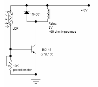
light activated relay

LIGHT ACTIWATED RELAY
This simple circuit using a single transistor turns ON the relay when light falls on the LDR.
The potentiometer is adjusted for the required sensitivity.
The power supply is 6V.
Be careful about the impedance of the relay. Its impedance should not be less that 60ohm.
Its working can be explained as follows:
With the light falling on the LDR,its resistance is low and the transistor is saturated and turns the
relay ON.
When light is obstructed, the LDRs resistance becomes very high. The potentiometer shorts the
transistors
base to ground and it is cut off. Hence the relay is OFF.

Lie detector circuit

Here's a simple lie detector that can be built in a few minutes, but can be incredibly
useful when you want to know if someone is really telling you the truth. It is not as
sophisticated as the ones the professionals use, but it works. It works by measuring skin
resistance, which goes down when you lie.
Part Total Qty. Description Substitutions
R1 1 33K 1/4W Resistor
R2 1 5K Pot
R3 1 1.5K 1/4W Resistor
C1 1 1uF 16V Electrolytic Capacitor
Q1 1 2N3565 NPN Transistor
M1 1 0-1 mA Analog Meter
MISC 1 Case, Wire, Electrodes (See Nots)
1. The electrodes can be alligator clips (although they can be painful), electrode pads
(like the type they use in the hospital), or just wires and tape.
2. To use the circuit, attach the electrodes to the back of the subjects hand, about 1
inch apart. Then, adjust the meter for a reading of 0. Ask the questions. You know
the subject is lying when the meter changes.

Thursday, 1 December 2011

Laser communication

Description
This is a simple Laser communication system. It can transmit and receive
signal from any audio device.Communication distance is few meters. All
components are not critical. Transistor 2N2222 may be on the coolrib. Laser
diode is from laser pointer.

Laser based intruder alarm


You can use this laser-based
intruder alarm conveniently
at the entrance of a hall or any
other similar location to protect the
same from unauthorised access as and
when desired. Its range can be extended
further to protect the perimeter of a
building from unauthorised intrusion
by using a cascade arrangement of
multiple alarms.
The circuit consists of a transmitter
and a receiver.
The transmitter circuit (shown in
Fig. 1) is nothing but a laser diode
(LD1) driven by a 9V PP3 battery. The
output of IC1 is regulated 5V as long as
its input remains equal to or more than
7.5V, thus ensuring a constant drive
current for the laser diode. The battery
(Batt1) is connected to the circuit
through switch S1.
The laser diode (LD1) can be
replaced with a laser pointer (torch)
emitting red laser beam. The laser
pointer itself can be used as a transmitter.
The pointer has in-built series
resistance, on/off switch and battery.

Wednesday, 30 November 2011

Laser door alarm circuit

This laser door alarm is based on the inturreption of laser beam.a low cost laser beam is used as the
light beam
when somebody breaks the laser path the alarm will be generated for afew seconds

laser sound circuit

This circuit produces a weird "Laser Ray" sound and flashes a white LED at approx 5Hz:

Inverter for soldering iron

Here is a simple but inexpensive
inverter for using a small
soldering iron (25W, 35W,
etc) in the absence of mains supply. It
uses eight transistors and a few resistors
and capacitors.
Transistors T1 and T2 (each BC547)
form an astable multivibrator that produces
50Hz signal. The complementary
outputs from the collectors of transistors
T1 and T2 are fed to pnp Darlington
driver stages formed by transistor
 Lovely T.P.
Inverter for Soldering Iron
s.c. dwivedi
pairs T3-T5 and T4-T6 (utilising BC558
and BD140). The outputs from the
drivers are fed to transistors T7 and T8
(each 2N3055) connected for push-pull
operation. Use suitable heat-sinks for
transistors T5 through T8.
A 230V AC primary to 12V-0-12V,
4.5A secondary transformer (X1) is
used. The centre-tapped terminal of
the secondary of the transformer is
connected to the battery (12V, 7Ah),
while the other two terminals of the
secondary are connected to the collectors
of power transistors T7 and T8,
respectively.
When you power the circuit using
switch S1, transformer X1 produces
230V AC at its primary terminal. This
voltage can be used to heat your soldering
iron.
Assemble the circuit on a generalpurpose
PCB and house in a suitable
cabinet. Connect the
battery and transformer
with suitable
current-carrying
wires. On the front
panel of the box, fit
power switch S1 and
a 3-pin socket for connecting
the soldering
iron.
Note that the ratings
of the battery,
transistors T7 and
T8, and transformer
may vary as these all
depend on the load
(soldering iron). 

inter communication using lm 741


two this circuit like this uses as inter communication

Tuesday, 29 November 2011

HOUSE SECURITY SYSTEM LASER USED


Here is a low-cost, invisible laser
circuit to protect your house
from thieves or trespassers. A
laser pointer torch, which is easily available
in the market, can be used to operate
this device.
The block diagram of the unit shown
in Fig. 1 depicts the overall arrangement
for providing security to a house.
A laser torch powered by 3V powersupply
is used for generating a laser
beam. A combination of plain mirrors
M1 through M6 is used to direct the
laser beam around the house to form a
net. The laser beam is directed to finally
fall on an LDR that forms part of
the receiver unit as shown in Fig. 2.
Any interruption of the beam by a thief/
trespasser will result into energisation
of the alarm. The 3V power-supply circuit
is a conventional full-wave rectifier-
filter circuit. Any alarm unit that
operates on 230V AC can be connected
at the output.
The receiver
unit comprises
two identical
step-down transformers (X1 and X2), two
6V relays (RL1 and RL2), an LDR, a
transistor, and a few other passive components.
When switches S1 and S2 are
activated, transformer X1, followed by a
full-wave rectifier and smoothing capacitor
C1, drives relay RL1 through the
laser switch.
The laser beam should be aimed continuously
on LDR. As long as the laser
beam falls on LDR, transistor T1 remains
forward biased and relay RL1 is
thus in de-energised condition. When a
person crosses the line of laser beam,
relay RL1 turns on and transformer X2
gets power supply and RL2
energises. In this condition,
the laser beam will have no
effect on LDR and the alarm
will continue to operate as long
as switch S2 is on.
When the torch is switched
on, the pointed laser beam is
reflected from a definite point/
place on the periphery of the
house. Making use of a set of
properly oriented mirrors
one can form an invisible net
of laser rays as shown in the
block diagram. The final ray
should fall on LDR of the
circuit.
Note. LDR should be kept
in a long pipe to protect it from
other sources of light, and
its total distance from the
source may be kept limited to
500 metres.

FROST ALARMM

Description
A simple thermistor triggered switch with adjustable threshold. It triggers
with cold temperatures so may be used as a frost alarm or cold temperature
switch.
Circuit
Circuit Notes
The thermistor used has a resistance of 15k at 25°C and 45k at 0° Celsius. A
suitable bead type thermistor can be found in the Maplin catalogue. The
100k pot allows this circuit to trigger over a wide range of temperatures.
If using a different thermistor then the control should match the new
thermistor at its highest resistance, or be higher in value. The op-amp in this
circuit is the ubiquitous 741. It may be catalogued as LM741, CA741 etc, all
types will work. In this circuit it is used as a comparator. The non-inverting
input (pin 3) is biased to half the supply voltage. The non-inverting input is
connected to the junction of the thermistor and potentiometer. The control is
adjusted so that the circuit is on when the thermistor is at the required
temperature range. Once the thermistor is outside the temperature range its
resistance alters and the op-amp output changes from near full supply to
around 1 or 2 volts dc. There is insufficient voltage to turn on the transistor
and the relay will not energise.
A slight amount of hysteresis is provided by inclusion of the 270k resistor.
This prevents rapid switching of the circuit when the temperature is near to
the switching threshold.

FACTORY&POLICE SIREN


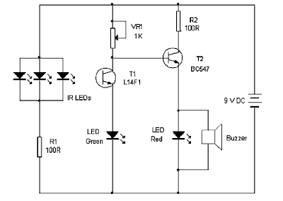
ENTRY ALARM

it gives a loud alarm when somebody crosses the invissible infrared barrier

ELECTRONIC THERMOMETER

This digital thermometer can
measure temperatures up to
150°C with an accuracy of ±1°C.
The temperature is read on a 1V full
scale-deflection (FSD) moving-coil
voltmeter or digital voltmeter.
Operational amplifier IC 741 (IC3)
provides a constant flow of current
through the base-emitter junction of
npn transistor BC108 (T1). The voltage
across the base-emitter junction
of the transistor is proportional to its
temperature. The transistor used this
way makes a low-cost sensor. You can
use silicon diode instead of transistor.
The small variation in voltage across
the base-emitter junction is amplified
by second operational amplifier (IC4),
before the temperature is displayed
on the meter. Preset VR1 is used to
set the zero-reading on the meter and
preset VR2 is used to set the range of
temperature measurement.
Operational amplifiers IC3 and IC4
operate off regulated ±5V power supply,
which is derived from 3-terminal
positive voltage regulator
IC 7805 (IC1) and
negative low-dropout
regulator IC 7660 (IC2).
The entire circuit works
off a 9V battery.
Assemble the circuit
on a general-purpose
PCB and enclose
in a small plastic box.
Calibrate the thermometer
using presets VR1
and VR2. After calibration,
keep the box in
the vicinity of the object
whose temperature is
to be measured. 

ELECTRICAL EQIPMENT CONTROLLING BY PC

Here is a novel idea
for using the printer
port of a PC, for control
application using software
and some interface
hardware. The interface circuit
along with the given
software can be used with
the printer port of any PC for
controlling up to eight equipment.
The interface circuit
shown in the figure is drawn
for only one device, being controlled by
D0 bit at pin 2 of the 25-pin parallel port.
Identical circuits for the remaining data

DOOR ALARM WITH COUNTER

Description
This circuit uses a synthesized sound chip from Holtek, the HT-2811.
This reproduces the sound of a "ding-dong" chiming doorbell.
Additionally, the circuit includes a CMOS 4026 counter display
driver IC to count your visitors.
Circuit Notes:
The Holtek HT-2811 is available from Maplin electronics in the UK, order code BH69A.
The operating voltage must remain within 2.4 to 3.3 Vdc and standby current is minimal.
The reset switch zeroes the count,and the 7 segment display is a common cathode type.
To save power consumption the display can be enabled or disabled with a switch as
shown in the above diagram. The count will still be held in memory. The IC pin out for
the 4026 is shown in pin order below:
Pin 1 is the clock input
Pin 2 is the clock enable
Pin 3 is display enable
Pin 4 enables the carry output
Pin 5 is the carry output
Pin 6 is display segment f Pin 7 is display segment g
Pin 8 is 0 V.
Pin 9 is display segment d Pin 10 is display segment a
Pin 11 is display segment e Pin 12 is display segment b

DIGITAL SECURITY CODE LOCK

Many digital code lock circuits
have been published in this
magazine. In those circuits a
set of switches (conforming to code) are
pressed one by one within the specified
time to open the lock. In some other
circuits, custom-built ICs are used and
positive and negative logic pulses are
keyed in sequence as per the code by
two switches to open the lock.
A low-cost digital code lock circuit
is presented in this article. Here the
keying-in code is rather unique. Six
switches are to be pressed to open the
lock, but only two switches at a time.
Thus a total of three sets of switches
have to be pressed in a particular sequence.
(Of these three sets, one set is
repeated.) The salient features of this
circuit are:
1. Use of 16 switches, which suggests
that there is a microprocessor inside.
2. Elimination of power amplifier
transistor to energise the relay.
3. Low cost and small PCB size.
A. JEYABAL
Simple Low-Cost
Digital Code Lock
An essential property of this electronic
code lock is that it works in
monostable mode, i.e. once triggered,
the output becomes high and remains
so for a period of time, governed by the
timing components, before returing to
the quiescent low state. In this circuit,
timer IC 555 with 8 pins is used. The
IC is inexpensive and easily available.
Its pin 2 is the triggering input pin
which, when held below 1/3 of the supply
voltage, drives the output to high
state. The threshold pin 6, when held
higher than 2/3 of the supply voltage,
drives the output to low state. By applying
a low-going pulse to the reset
pin 4, the output at pin 3 can be
brought to the quiescent low level. Thus
the reset pin 4 should be held high for
normal operation of the IC.
Three sets of switches SA-SC, S1-
S8 and S3-S4 are pressed, in that order,
to open the lock. On pressing the
switches SA and SC simultaneously, capacitor
C3 charges through the potential
divider comprising resistors R3 and
R4, and on releasing these two switches,
capacitor C3 starts discharging through
resistor R4. Capacitor C3 and resistor
R4 are so selected that it takes about
five seconds to fully discharge C3.
Depressing switches S1 and S8 in
unison, within five seconds of releasing
the switches SA and SC, pulls pin 2 to
ground and IC 555 is triggered. The capacitor
C1 starts charging through resistor
R1. As a result, the output (pin
3) goes high for five seconds (i.e. the
charging time T of the capacitor C1 to
the threshold voltage, which is calculated
by the relation T=1.1 R1 x C1 seconds).
Within these five seconds, switches
SA and SC are to be pressed momentarily
once again, followed by the depression
of last code-switch pair S3-S4.
These switches connect the relay to output
pin 3 and the relay is energised.
The contacts of the relay close and the
solenoid pulls in the latch (forming part
of a lock) and the lock opens. The remaining
switches are connected between
reset pin 4 and ground. If any one of
these switches is pressed, the IC is reset
and the output goes to its quiescent
low state. Possibilities of pressing these
reset switches are more when a code
breaker tries to open the lock.
LED D5 indicates the presence of
power supply while resistor R5 is a current
limiting resistor.
The given circuit can be recoded easily
by rearranging connections to the
switches as desired by the user.

AC MAINS BI STABLE SWITCH

This AC mains-operated bistable
switch turns on or turns off a
device using a miniature neon
lamp and a few discrete components.
This switch can be used for control panels,
appliances and lighting controls.
A push-to-on switch is used to
light up the neon lamp. The light emitted
by the neon lamp, in turn, enables
the switching action of the circuit. Use
of a 555 timer wired for bistable operation
makes the circuit act as a bistable
switch.
The neon lamp (NL1) and the
push-to-on switch (S1) are directly connected
to 230V AC mains. The 12V DC
supply for timer 555 (IC1) is derived
from 230V AC mains through capacitive
dropper C1, resistor R1 and a 12V
zener diode. IC1 works as a flip-flop
circuit, with the signal at its output
pin 3 toggling every time it receives a
pulse at its pins 2 and 6.
The operation of the circuit is simple.
When you press switch S1 momentarily,
the neon lamp glows, making
phototransistor T1 conduct to provide
a pulse at pins 2 and 6 of IC1. when
 T.A. Babu
AC Mains Bistab le Switc h
s.c. dwivedi
switch S1 is pressed, the output of IC1
goes high and LED1 glows. Pressing S1
again makes the output of IC1 low and
LED1 stops glowing.
In place of LED1, you can use an
opto-diac or suitable relay (not shown
in the circuit) along with a suitable
driver circuit to drive AC loads.
Assemble the circuit on a generalpurpose
PCB with the neon lamp and
the phototransistor housed in a small
black tube isolated from the external
light source, and enclose in a suitable
cabinet. Fix switch S1 on the
front panel of the cabinet,
and mains power cord at
the rear. At the rear, also fix
a 3-pin socket to connect the
AC load.
Caution. Take care
when operating this circuit
as it is directly connected to
230V AC mains. Better still,
don’t attempt this circuit
if you have no experience
in handling high-voltage
circuits. 

5-30 minute timer circuit

Notes:
Simple to build, simple to make, nothing too complicated here. However you must use
the CMOS type 555 timer designated the 7555, a normal 555 timer will not work here
due to the resistor values. Also a low leakage type capacitor must be used for C1, and I
would strongly suggest a Tantalum Bead type. Switch 3 adds an extra resistor in series to
the timing chain with each rotation, the timing period is defined as :-
Timing = 1.1 C1 x R1
Note that R1 has a value of 8.2M with S3 at position "a" and 49.2M at position "f". This
equates to just short of 300 seconds for each position of S3. C1 and R1 through R6 may be
changed for different timing periods. The output current from Pin 3 of the timer, is
amplified by Q1 and used to drive a relay. The relay contacts give physical and electrical
separation and may be used to switch circuits using higher current or voltage.
Alternatively if an audible or visual output is desired then the relay may be substituted for
a buzzer or LED.
Breadboard Layout:
As a first realisation I made a layout on breadboard. The rotary switch, relay and driver
transistor were omitted, the parts being replaced by a single red LED and 2.7k resistor
(see below).

INFRARED TOY CAR MOTOR CONTROLLER

This add-on circuit enables remote
switching on/off of battery-operated
toy cars with the help of a TV/
video remote control handset operating at
30–40 kHz.
When the circuit is energised
from a 6V battery, the decade
counter CD4017 (IC2), which is
configured as a toggle flip-flop, is
immediately reset by the power-onreset
combination of capacitor C3
and resistor R6. LED1 connected
to pin 3 (Q0) of IC2 via resistor R5
glows to indicate the standby condition.
In standby condition, data
output pin of the integrated infrared
receiver/demodulator
(SFH505A or TSOP1738) is at a
high level (about 5 volts) and transistor
T1 is ‘off’ (reverse biased).
The monostable wired around IC1
is inactive in this condition.
When any key on the remote
control handset is depressed, the
output of the IR receiver momentarily
transits through low state and
transistor T1 conducts. As a result,
the monostable is triggered and a
short pulse is applied to the clock
input (pin 14) of IC2, which takes Q1 output
(pin 2) of IC2 high to switch on motor
driver transistor T2 via base bias resistor
R7 and the motor starts rotating
continously (car starts running). Resistor
R8 limits the starting current.
When any key on the handset is

1 TRANSISTER LED FLASH AND LM 3909 LED FLASHER

Here is a one transistor LED flasher circuitwhich will flash a super bright LED. The
circuit is using single transistor as driver which is taking flash rate from the LED 2 which
is a self flashing LED. The flash rate can be adjusted by changing the value of 1k resistor
used in the circuit. The circuit is using 2N3904transistor but you can use any NPN
transistor available with you. The input power can be from any 6V DC battery or


LM 3909 LED FLASHER


PARTS LIST
C1=100nf electrolytic capacitor
IC1=LM3909 led flasher IC
led 1=red led
1.5 v battery

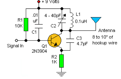
BASIC RF OSCILLATOR


This basic circuit is easy to build and the components are not critical.most of them are found in your junk box
the L1 antena coil can be made by close winding8 to 10 turns of 22 gauges insulated hookup wire around a1/4 inch form such as a pencil.you can expiriment with size the coil and the no of turns to see how it affects the frequency and signal output of the oscillator you should be able to pick up its signal with a standard FM radio reciever.The signal in should be coupled by a disk capasitor of about 0.1nf to the stage in front of it

ALTERNATING ON-OFF SWITCH

ERROR FIX: The LED (Led1) was drawn up-side-down. Fixed.
Parts List
Resistors are carbon, 1/4 Watt, 5% tolerance.
R1 = 10K
R2 = 100K
R3 = 10K
R4 = 220 Ohm (optional)
C1 = 0.1μF, Ceramic (100nF)
C2 = 1μF/16V, Electrolytic
D1 = 1N4001 (see text)
Led1 = Led, 3mm, red (optional)
Q1 = 2N4401 (see text)
IC1 = 4069, CMOS, Hex Inverter (MC14069UB), or equivalent
S1 = Momentary on-switch
Ry1 = Relay (see text)
Use this circuit instead of a standard on-off switch. Switching is very gentle. Connect unused input pins to an appropriate
logic level (I used ground). Unused output pins *MUST* be left open!
First 'push' activates the relay, another 'push' de-activates the relay.
IC1, the MC14069 (or 4069) is a regular Hex-inverter type and is constructed with MOS P-channel and N-channel
enhancement mode devices in a single monolithic structure. It will operate on voltages from 3 to 18 volts, but most
applications are in the 5 to 15 volts. Although the 4069 contains protection circuitry agains damage from ESD (Electro
Static Discharge), use common sense when handling this device. Depending on your application you may want to use an
IC-socket with IC1. It makes replacement easy if the IC ever fails.
You can use any type of 1/4 watt resistors including the metal-film type.
The type for D1 in not critical, even a 1N4148 will work. But, depending on your application I would suggest a 1N4001
(or similar) as a minimum.
Any proper replacement for Q1 will work, including the european TUN's. Since Q1 is just a driver to switch the relay coil,
almost any type for the transistor will do. PN100, NTE123A, 2N3904, 2N2222, 2N4013, etc. will all work.
For C2, if you find the relay acts not fast enough, you can change it to a lower value or use a ceramic cap of around 0.1μF.
It is there as a spark-arrestor together with the diode (D1).
For the relay I used a 6 volt type with the above circuit and 9 volt battery. The circuit will work fine with 12 Volt, the only
thing to watch for is the working voltage of C2; increase that to 25V if you use a 12V supply.
I added the Led to have a visual indication of being 'on'. For use with 12V supply make R4 390 ohms. The LED and R4
are of course optional and can be left out. Your application may already have some sort of indicator and so the LED and
R4 are not needed.

welcome to muhammed shanif's electronics circuits blog


HERE IS THE LOTS OF ELECTRONICS CIRCUITS