Saturday 3 December 2011

Radiation sensor


here is the simple tool to check the degree of radiation from an electric or electronic instrument
.The led s in the circuit will give a running light pattern at the momemt the circuit sences electromagnetic
radiation from the device.it can detect the radiation from the computer or telivision from a distance of 2feet or more

pyro electric fire alarm

Here is an ultra-sensitive fire
sensor that exploits the direct
piezoelectric property of an
ordinary piezo element to detect fire.
The lead zirconate titanate crystals in
the piezo element have the property
to deform and generate an electric
potential when heated, thus converting
the piezo element into a heat sensor.
The circuit described here is very
sensitive. It gives a warning alarm if
the room temperature increases more
than 10°C. The entire circuit has two
sections—the sensor and the power
supply section.

protection for your electrical appliances

Here is a very low-cost circuit to
save your electrically operated
appliances, such as TV, tape
recorder, refrigerator, and other
instruments during sudden tripping and
resumption of mains supply. Appliances
like refrigerators and air-conditioners are
more prone to damage due to such
conditions.

Friday 2 December 2011

power failure alarm

Description
This is a very basic alarm designed to let you know when the electricity supply fails. The
alarm is powered from a battery which uses no current consumption at all in standby, a
battery should therefore last its full shelf life.

Pc over heat alarm


If your PC overheats, it could
damage its expensive components.
Here’s a circuit that warns you of
your PC getting heated.
Today’s computers contain most
of the circuitry on just a few chips
and reduced power consumption is
a byproduct of this LSI and VSLI
approach. Some PCs still have
power supplies that are capable of
supplying around 200W, but few
PCs actually consume power to this
extent.
On the other hand, apart from
some portable and small desktop computers
that use the latest micro-power
components, most PCs still consume
significant amount of power and generate
certain amount of heat.

Mini ups system

This circuit provides an uninterrupted
power supply (UPS)
to operate 12V, 9V and 5V
DC-powered instruments at up to 1A
current. The backup battery takes up
the load without spikes or delay when
the mains power gets interrupted. It
can also be used as a workbench power
supply that provides 12V, 9V and 5V
operating voltages. The circuit immediately
disconnects the load when
the battery voltage reduces to 10.5V to
prevent deep discharge of the battery.
LED1 indication is provided to show
the full charge voltage level of the battery.
miniature white LEDs (LED2 and
LED3) are used as emergency lamps
during power failure at night.

Lpg gas leakage detector


LPG gas is supplied in pressurised
steel cylinders. As this gas
is heavier than air, when it leaks
from a cylinder it flows along floor
and tends to settle in low spots such
as a basement. This can cause fire or
suffocation if not dealt with.
Here is a circuit that detects the
leakage of LPG gas and alerts the user
through audio-visual indications.

Low voltage alarm

Part Total Qty. Description Substitutions
R1, R3 2 1K 1/4W Resistor
R2 1 5K Pot
U1 1 LM339 Op Amp IC
D1 1 1N5233B Zener Diode
D2 1 LED
BZ1 1 Piezo Buzzer
MISC 1 Board, wire, socket for IC
Notes
1. The circuit will operate from 9V to 12V.
2. Adjust R2 until the alarm goes off at the correct voltage.

Low cost transisterised intercom


Several intercom circuits have appeared
in EFY using integrated
circuits. The circuit described here
uses three easily available transistors
only. Even a beginner can easily assemble
it on a piece of veroboard.
The circuit comprises a 3-stage resistor-
capacitor coupled amplifier. When
ring button S2 is pressed, the amplifier
circuit formed around transistors T1 and
T2 gets converted into an asymmetrical
astable multivib-rator generating ring
signals. These ring signals are amplified
by transistor T3 to drive the speaker of
earpiece.
Several circuits for constructing FM
transmitters have been published
in EFY. The power output of most
of these circuits were very low because
no power amplifier stages were incorporated.
The transmitter circuit described here
has an extra RF power amplifier stage,
after the oscillator stage, to raise the
power output to 200-250 milliwatts. With
a good matching 50-ohm ground—plane
antenna or multi-element Yagi antenna,
this transmitter can provide reasonably
good signal strength up to a distance of
about 2 kilometres.
The circuit built around transistor
T1 (BF494) is a basic low-power variable-
frequency VHF oscillator. A varicap
diode circuit is included to change the frequency
of the transmitter and to provide
frequency modulation by audio signals.
The output of the oscillator is about 50
milliwatts. Transistor T2 (2N3866) forms
a VHF-class A power amplifier. It boosts
the oscillator signals’ power four to five
times. Thus, 200-250 milliwatts of power
is generated at the collector of transistor
T2.
For better results, assemble the circuit
on a good-quality glass epoxy board and
house the transmitter inside an aluminium
case. Shield the oscillator stage using
an aluminium sheet.
Coil winding details are given below:
L1 – 4 turns of 20 SWG wire close
wound over 8mm diameter plastic
former.
L2 – 2 turns of 24 SWG wire near top
end of L1.
(Note: No core (i.e. air core) is used for
the above coils)
L3 – 7 turns of 24 SWG wire close
wound with 3mm diameter air core.
L4 – 7 turns of 24 SWG wire-wound on
a ferrite bead (as choke)
Potentiometer VR1 is used to set the
centre frequency whereas potentiometer
VR2 is used for power control. For humfree
operation, operate the transmitter
on a 12V rechargeable battery pack of
10 x 1.2-volt Ni-Cd cells. Transistor T2
must be mounted on a heat sink. Do
not switch on the transmitter without
a matching antenna. Adjust both trimmers
(VC1 and VC2) for maximum
transmission power. Adjust potentiometer
VR1 to set the centre frequency
near 100 MHz.
This transmitter should only be used
for educational purposes. Regular transmission
using such a transmitter without
a licence is illegal in India.

locker guard circuit

protect your lock or briefcase from theft using this poket sized gadget .it gives a load police
siren to catch attention

electronic digital lock circuit


combination lock with auto reset


light activated relay

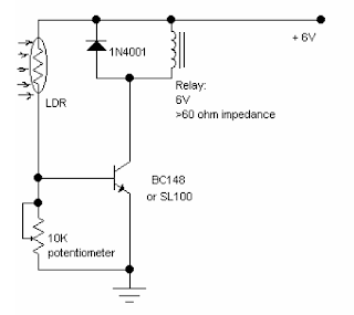
LIGHT ACTIWATED RELAY
This simple circuit using a single transistor turns ON the relay when light falls on the LDR.
The potentiometer is adjusted for the required sensitivity.
The power supply is 6V.
Be careful about the impedance of the relay. Its impedance should not be less that 60ohm.
Its working can be explained as follows:
With the light falling on the LDR,its resistance is low and the transistor is saturated and turns the
relay ON.
When light is obstructed, the LDRs resistance becomes very high. The potentiometer shorts the
transistors
base to ground and it is cut off. Hence the relay is OFF.

Lie detector circuit

Here's a simple lie detector that can be built in a few minutes, but can be incredibly
useful when you want to know if someone is really telling you the truth. It is not as
sophisticated as the ones the professionals use, but it works. It works by measuring skin
resistance, which goes down when you lie.
Part Total Qty. Description Substitutions
R1 1 33K 1/4W Resistor
R2 1 5K Pot
R3 1 1.5K 1/4W Resistor
C1 1 1uF 16V Electrolytic Capacitor
Q1 1 2N3565 NPN Transistor
M1 1 0-1 mA Analog Meter
MISC 1 Case, Wire, Electrodes (See Nots)
1. The electrodes can be alligator clips (although they can be painful), electrode pads
(like the type they use in the hospital), or just wires and tape.
2. To use the circuit, attach the electrodes to the back of the subjects hand, about 1
inch apart. Then, adjust the meter for a reading of 0. Ask the questions. You know
the subject is lying when the meter changes.

Thursday 1 December 2011

Laser communication

Description
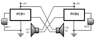
This is a simple Laser communication system. It can transmit and receive
signal from any audio device.Communication distance is few meters. All
components are not critical. Transistor 2N2222 may be on the coolrib. Laser
diode is from laser pointer.

Laser based intruder alarm


You can use this laser-based
intruder alarm conveniently
at the entrance of a hall or any
other similar location to protect the
same from unauthorised access as and
when desired. Its range can be extended
further to protect the perimeter of a
building from unauthorised intrusion
by using a cascade arrangement of
multiple alarms.
The circuit consists of a transmitter
and a receiver.
The transmitter circuit (shown in
Fig. 1) is nothing but a laser diode
(LD1) driven by a 9V PP3 battery. The
output of IC1 is regulated 5V as long as
its input remains equal to or more than
7.5V, thus ensuring a constant drive
current for the laser diode. The battery
(Batt1) is connected to the circuit
through switch S1.
The laser diode (LD1) can be
replaced with a laser pointer (torch)
emitting red laser beam. The laser
pointer itself can be used as a transmitter.
The pointer has in-built series
resistance, on/off switch and battery.